SIGN IN YOUR ACCOUNT TO HAVE ACCESS TO DIFFERENT FEATURES

FORGOT YOUR PASSWORD?

FORGOT YOUR DETAILS?

AAH, WAIT, I REMEMBER NOW!
QUESTIONS? Contact Us | 866-824-4459

ZenTek ConsultantsZenTek Consultants

  • Architecture
    • Services
      • TEK Bloks
      • BIM Services
      • CAD Standards Service
      • Civil 3D Kickstart
      • BricsCAD Pilot Program
      • Moving to BricsCAD
      • Bluebeam Tool Chest Customization Services
      • Construction Support Services
      • Microsoft 365 Implementation
      • Microsoft Teams Services
      • SharePoint Online Services
    • Training Options
      • Autodesk Revit Online Courses
      • AutoCAD Online Courses
      • AutoCAD Civil 3D Online Courses
      • Autodesk 3ds Max Online Courses
      • Autodesk Navisworks Online Courses
      • BricsCAD Online Courses
      • Bluebeam Revu Online Courses
      • Microsoft Online Courses
      • Custom Training
      • Training Waitlist
    • Software
      • BricsCAD
      • Bricsys 24/7
      • Bluebeam Revu
      • Microsoft
  • Engineering
    • Services
      • TEK Bloks
      • CAD Standards Service
      • BIM Services
      • Civil 3D Kickstart
      • BricsCAD Pilot Program
      • Moving to BricsCAD
      • Microsoft 365 Implementation
      • Microsoft Teams Services
      • SharePoint Online Services
    • Training Options
      • AutoCAD Civil 3D Online Courses
      • AutoCAD Online Courses
      • Autodesk Revit Online Courses
      • BricsCAD Online Courses
      • Civil Site Design Online Courses
      • Bluebeam Revu Online Courses
      • Microsoft Online Courses
      • Custom Training
      • Training Waitlist
    • Software
      • Civil Site Design
      • Stringer Topo
      • BricsCAD
      • Bricsys 24/7
      • Bluebeam Revu
      • Microsoft
  • Construction
    • Services
      • TEK Bloks
      • Bluebeam Tool Chest Customization Services
      • Construction Support Services
      • Services for Procore
      • BIM Services
      • CAD Standards Service
      • Civil 3D Kickstart
      • BricsCAD Pilot Program
      • Moving to BricsCAD
      • Microsoft 365 Implementation
      • Microsoft Teams Services
      • SharePoint Online Services
    • Training Options
      • Bluebeam Revu Online Courses
      • Procore Online Courses
      • AutoCAD Online Courses
      • Autodesk Revit Online Courses
      • Autodesk Navisworks Online Courses
      • Autodesk 3ds Max Online Courses
      • AutoCAD Civil 3D Online Courses
      • BricsCAD Online Courses
      • Civil Site Design Online Courses
      • Microsoft Online Courses
      • Custom Training
      • Training Waitlist
    • Software
      • Bluebeam Revu
      • ZenEstimate Tools
      • ZenTek Revu Tools
      • Procore
      • Civil Site Design
      • Stringer Topo
      • BricsCAD
      • Bricsys 24/7
      • Microsoft
  • Manufacturing
    • Training Options
      • AutoCAD Online Courses
      • BricsCAD Online Courses
      • Microsoft Online Courses
      • Custom Training
      • Training Waitlist
    • Software
      • BricsCAD
      • Bricsys 24/7
      • Bluebeam Revu
      • Microsoft
  • Events
    • Upcoming Events
    • Live Webinars
    • On-Demand Webinars
  • Resources
    • Blog
    • The CADDLE Call Podcast
    • YouTube Channel
    • Planswift Training: Planswift Pros
    • Promotions
  • About Us
    • News
    • Contact Us

BricsCAD Sheet Metal and Direct Modeling – How Does It Work?

ZenTek Consultants
Tuesday, 09 June 2020 / Published in BricsCAD, Product Design and Manufacturing

BricsCAD Sheet Metal and Direct Modeling – How Does It Work?

BricsCAD Sheet Metal

Every major 3D CAD platform with sheet metal capabilities works the same. You start with a base flange and use its edges to add more flanges to it. Once you’re done adding flanges and other details such as corner rounds and hems, you are given an unfolded model. Simple, right? However, this overlooks a fundamental problem of design intent: what if you weren’t sure the part you are designing will be manufactured from sheet metal? BricsCAD has a solution.

By its nature, sheet metal modeling has always been parametric. There are presets that must be used for calculating elements like bend radii and corner reliefs. Most CAD platforms adhere to this “flange-by-flange” approach, and it works well enough, until small tweaks and adjustments become necessary. Systems with limited direct modeling capability may allow you to make these tweaks but only after removing any sheet metal structure from your document. And in the case of Autodesk Inventor, you may not even be able to use parametric solid modeling commands without causing errors in the sheet metal.

BricsCAD Sheet Metal

In contrast, BricsCAD values design intent of its users by making it easy to switch from solid modeling to sheet metal midway through the design. Here’s how:

After your part has been modeled, use the Shell tool to remove material from the inside of the part. When choosing the shell offset, make sure to use the same value as the Sheet Thickness default specified for your file. Failing to do so will cause an error during the next step. Keep in mind that when prompted to remove faces while shelling, you don’t have to remove any. This is useful if your sheet metal part is a full enclosure.

Now that the entire part is of a constant thickness, we are ready to convert to sheet metal. Navigate to the Sheet Metal ribbon tab and run the “Convert to Sheet Metal” command. BricsCAD will automatically detect which parts of your model should be represented as flanges and will color code their faces respectively.

Before building the rest of the sheet metal features, use the Repair command to tweak the edges of your sheet. If your part contained tapers, lofts, or sweeps, it is possible that the edges are not perpendicular to their flange faces. The Repair command should correct this quickly.

Now we are ready to start adding bends. You can place bends manually by picking edges to convert to bends, or you can automatically convert all edges to bends in a single command.

Take your time with this next step and inspect your model for junction placements. If your component is an enclosure, it will need to contain junctions alongside the bends. Failing to place enough junctions will result in errors when unfolding your model. You can also convert an existing bend to a junction by selecting it. It should be easy to navigate your model, as all sheet metal components such as bends, junctions and edges are color coded appropriately. You can also add other sheet metal features during this step, such as miter cuts and tab joints. By using the Sheet Metal Browser, you can right click on edge features and convert them, for example you can convert a junction back into a bend.

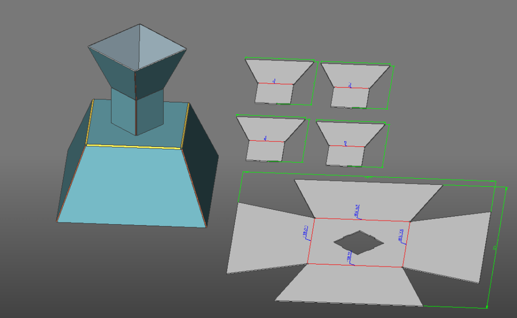
Once you are done, use the unfold tool to flatten your model. Note that the flattened model can be dropped directly into the same file, and comes fully annotated with overall dimensions and bend information. If your design contains multiple sheet metal pieces, each piece will be separated when unfolding. If a piece does not unfold fully, or gives an error, recheck your bend and junction placements.

Direct modeling offers flexibility to add other parts to your design, or begin treating it as a compound assembly containing sheet metal and solid parts. Simply use any solid modeling command on your model to add geometry, and apply a direct modeling technique of your choice to modify it. Remember, everything in BricsCAD uses the same format, so you can add as many parts as you like, regardless of the design method.

These are just some of the features of BricsCAD’s powerful Sheet Metal tool group.

What you can read next

The CADDle Call podcast
Training CAD Staff – There’s a Better Way
The CADDle Call podcast
Building Products Manufacturing – Getting Your Product Easily Specified & Ordered
The CADDle Call podcast
AutoCAD – It’s Not Your Only 2D CAD Option

Leave a Reply Cancel reply

Your email address will not be published. Required fields are marked *

Recent Posts

  • Gradings in AutoCAD Civil 3D

  • The CADDle Call podcast

    What’s New in the Autodesk World

  • Easy Electrical Circuits Using Revit

  • The CADDle Call podcast

    Young Engineers & Designers – What’s Missing from Their Education

  • Bluebeam Revu: Creating a Master Table of Contents

Categories

Archives

  • Services
  • Software
  • Online Training
  • Leasing Options
  • About Us
  • Contact Us
  • Privacy Policy
  • Events
  • The CADDle Call Podcast
  • Blog
  • YouTube Channel
  • Promotions
  • Subscribe to Emails

Official Bricsys Reseller

Bluebeam Partner

Procore Certified Consultant

ACCNJ Member

  • GET SOCIAL

©2016 - 2021 ZENTEK. LLC TOP